Difference between revisions of "RPiWaterMeter"
| Line 4: | Line 4: | ||
<br><br> | <br><br> | ||
It works with a magnetic sensor, which can be used because of the half-metal rotor of watermeters in my country (Netherlands)<br> | It works with a magnetic sensor, which can be used because of the half-metal rotor of watermeters in my country (Netherlands)<br> | ||
| − | For magnetic sensor I use the LJ12A3-4-Z/B from the well known company in China. You can use most types but be sure to by the OC (Open-Collector) version, while most sensors use higher voltages than a Raspberry Pi. | + | For magnetic sensor I use the LJ12A3-4-Z/B from the well known company in China. <br> |
| + | You can use most types but be sure to by the OC (Open-Collector) version, while most sensors use higher voltages than a Raspberry Pi. | ||
<br><br> | <br><br> | ||
| − | |||
With a piece of aluminium it's easy to mount on the meter: | With a piece of aluminium it's easy to mount on the meter: | ||
<div class="res-img"> | <div class="res-img"> | ||
[[File:RPi_watermeter_sensor.jpeg|640px]] | [[File:RPi_watermeter_sensor.jpeg|640px]] | ||
</div> | </div> | ||
| − | + | <br> | |
Shematics: | Shematics: | ||
<div class="res-img"> | <div class="res-img"> | ||
| Line 17: | Line 17: | ||
</div> | </div> | ||
Because the sensor needs 9-36 Volt, while a Raspberry Pi only can deliver 5 Volt, I use an adjustable chopper (also from China), adjusted as 12 Volt.<br> | Because the sensor needs 9-36 Volt, while a Raspberry Pi only can deliver 5 Volt, I use an adjustable chopper (also from China), adjusted as 12 Volt.<br> | ||
| − | The output is connected to one of the GPIO, which first should configured as input, I use GPIO28 (pin38). | + | The output is connected to one of the GPIO, which first should configured as input, I use GPIO28 (pin38).<br> |
| − | The led will show if it works, for every pulse 1 liter water is detected. | + | The led will show if it works, for every pulse 1 liter water is detected.<br> |
| − | I use a Raspberry Pi Cluster, so I can do a failover, pin 2,6 and 38 are also wired to a second Pi, for the Power a diode is needed, for each Pi, while it's a bad idea to connect the power to multiple Pi's. | + | I use a Raspberry Pi Cluster, so I can do a failover, pin 2,6 and 38 are also wired to a second Pi,<br> |
| − | + | for the Power a diode is needed, for each Pi, while it's a bad idea to connect the power to multiple Pi's. | |
| + | <br><br> | ||
First tested it with an experiment board: | First tested it with an experiment board: | ||
<div class="res-img"> | <div class="res-img"> | ||
[[File:RPi_watermeter_experiment.jpeg|640px]] | [[File:RPi_watermeter_experiment.jpeg|640px]] | ||
</div> | </div> | ||
| − | To test it on a pi you need the gpio command: | + | To test it on a pi you need the gpio command:<br> |
| − | if not installed: | + | if not installed:<br> |
| − | sudo apt-get update | + | sudo apt-get update<br> |
| − | sudo apt-get install wiringpi | + | sudo apt-get install wiringpi<br> |
| − | change GPIO 28 (BCM=20 an pin=38) as input: | + | change GPIO 28 (BCM=20 an pin=38) as input:<br> |
| − | sudo /usr/local/bin/gpio export 20 in | + | sudo /usr/local/bin/gpio export 20 in<br> |
| − | Put this line somewhere in a startup file, so it will stay that way, after reboot, best below in /etc/rc.local (without sudo) | + | Put this line somewhere in a startup file, so it will stay that way, after reboot,<br> |
| − | to show the states: | + | best below in /etc/rc.local (without sudo)<br> |
| − | sudo gpio readall | + | to show the states:<br> |
| − | + | sudo gpio readall<br> | |
| − | + | <br><br> | |
| − | + | ||
| − | + | ||
This is the result: | This is the result: | ||
| Line 43: | Line 42: | ||
[[File:RPi_watermeter_board.jpeg|640px]] | [[File:RPi_watermeter_board.jpeg|640px]] | ||
</div> | </div> | ||
| − | I use a RJ11 connector to connect the sensor. | + | I use a RJ11 connector to connect the sensor. <br> |
| − | + | <br> | |
Complete mounted on the Pi: | Complete mounted on the Pi: | ||
<div class="res-img"> | <div class="res-img"> | ||
[[File:RPi_watermeter_complete.jpeg|640px]] | [[File:RPi_watermeter_complete.jpeg|640px]] | ||
</div> | </div> | ||
Revision as of 18:11, 23 December 2020
Water usage mesurement with a Raspberry Pi
In my case I use Domoticz, but it also works with Home-Assist and other products.
It works with a magnetic sensor, which can be used because of the half-metal rotor of watermeters in my country (Netherlands)
For magnetic sensor I use the LJ12A3-4-Z/B from the well known company in China.
You can use most types but be sure to by the OC (Open-Collector) version, while most sensors use higher voltages than a Raspberry Pi.
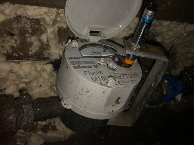
With a piece of aluminium it's easy to mount on the meter:
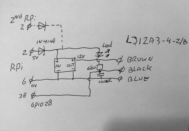
Shematics:
Because the sensor needs 9-36 Volt, while a Raspberry Pi only can deliver 5 Volt, I use an adjustable chopper (also from China), adjusted as 12 Volt.
The output is connected to one of the GPIO, which first should configured as input, I use GPIO28 (pin38).
The led will show if it works, for every pulse 1 liter water is detected.
I use a Raspberry Pi Cluster, so I can do a failover, pin 2,6 and 38 are also wired to a second Pi,
for the Power a diode is needed, for each Pi, while it's a bad idea to connect the power to multiple Pi's.
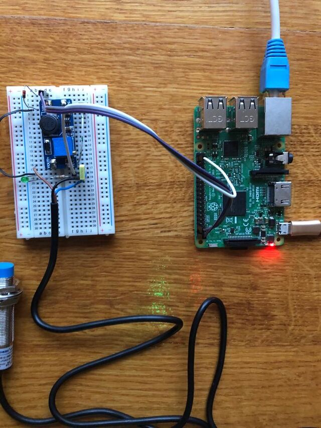
First tested it with an experiment board:
To test it on a pi you need the gpio command:
if not installed:
sudo apt-get update
sudo apt-get install wiringpi
change GPIO 28 (BCM=20 an pin=38) as input:
sudo /usr/local/bin/gpio export 20 in
Put this line somewhere in a startup file, so it will stay that way, after reboot,
best below in /etc/rc.local (without sudo)
to show the states:
sudo gpio readall
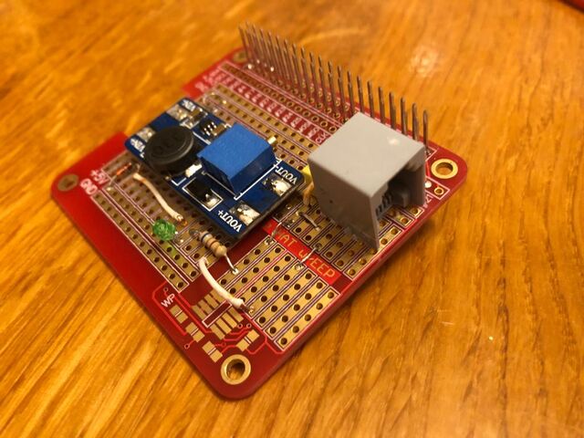
This is the result:
I use a RJ11 connector to connect the sensor.
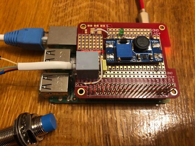
Complete mounted on the Pi:
