Difference between revisions of "RPiWaterMeter"
| (32 intermediate revisions by the same user not shown) | |||
| Line 1: | Line 1: | ||
| − | ''' | + | '''Water usage measurement with a Raspberry Pi'''<br> |
| − | + | In my case I use Domoticz, but it also works with Home-Assist and other products. | |
| − | + | <br><br> | |
| − | It works with a magnetic sensor, which can be used because of the half-metal rotor of watermeters in my country (Netherlands) | + | It works with a magnetic sensor, which can be used because of the half-metal rotor of watermeters in my country (Netherlands)<br> |
| − | For magnetic sensor I use the LJ12A3-4-Z/B | + | For magnetic sensor I use the LJ12A3-4-Z/B from the well known company in China. <br> |
| + | You can use most types but be sure to buy the OC (Open-Collector) version, because most sensors use higher voltages than the Raspberry Pi, and you won't damage your Pi.<br><br> | ||
| + | The sensor should be placed on the side of the rotator, not in the middle. | ||
| + | <br><br> | ||
| + | With a piece of aluminium it's easy to mount on the meter: | ||
<div class="res-img"> | <div class="res-img"> | ||
| − | [[File:RPi_watermeter_sensor.jpeg| | + | [[File:RPi_watermeter_sensor.jpeg|640px]] |
</div> | </div> | ||
| − | + | <div class="res-img"> | |
| + | [[File:RPi_watermeter_beugel.jpeg|320px]] | ||
| + | </div> | ||
| + | <br> | ||
Shematics: | Shematics: | ||
<div class="res-img"> | <div class="res-img"> | ||
| − | [[File:RPi_watermeter_schematics.jpeg]] | + | [[File:RPi_watermeter_schematics.jpeg|640px]] |
</div> | </div> | ||
| + | The sensor needs 9-36 Volt, a Raspberry Pi only can deliver 5 and 3.3 Volt.<br> | ||
| + | You can use an extra 12 Volt adapter, but I don't like that......<br> | ||
| + | I use an adjustable chopper board (also from China), adjusted as 12 Volt.<br> | ||
| + | If you want the same Board it's called:<br> | ||
| + | "MT3608 DC-DC Adjustable Boost Module Feed Converter Voltage Regulator Module 2A Max 2 V-24 V to 5 V-28 V"<br> | ||
| + | Update: There are also sensors working at 5 Volt, this is a lot easier. In the time I build this, I didn't find them.<br> | ||
| + | <br> | ||
| + | The output is connected to one of the GPIO's of the Pi, which first should configured as input, in my case I use GPIO28 (pin38/BCM20).<br> | ||
| + | The led will show if it works, for every pulse 1 liter water is detected.<br><br> | ||
| + | The diode is not needed if you use 1 Pi.<br> | ||
| + | I use a Raspberry Pi Cluster, so I can do a failover.<br> | ||
| + | The board is connected on 1 Pi, the other Pi is connected to the same pins: 6 and 38.<br> | ||
| + | For the Power (pin 2) a diode is needed, 1 for each Pi, while it's a bad idea to connect the power to multiple Pi's. | ||
| + | <br><br> | ||
| + | First tested it with an experiment board: | ||
| + | <div class="res-img"> | ||
| + | [[File:RPi_watermeter_experiment.jpeg|640px]] | ||
| + | </div> | ||
| + | To test it on a pi you need the gpio command:<br> | ||
| + | if not installed:<br> | ||
| + | sudo apt-get update<br> | ||
| + | sudo apt-get install wiringpi<br> | ||
| + | change GPIO 28 (BCM=20 and pin=38) as input:<br> | ||
| + | sudo /usr/local/bin/gpio export 20 in<br> | ||
| + | Put this line somewhere in a startup file, so it will stay that way, after reboot,<br> | ||
| + | best below in /etc/rc.local (without sudo)<br> | ||
| + | to show the states:<br> | ||
| + | sudo gpio readall<br> | ||
| + | <br><br> | ||
| + | |||
| + | This is the result: | ||
| + | <div class="res-img"> | ||
| + | [[File:RPi_watermeter_board.jpeg|640px]] | ||
| + | </div> | ||
| + | All welded on an experiment board, for the Rpi, with a long pin connector, so you can stack other boards.<br> | ||
| + | I use a RJ11 connector to connect the sensor. <br> | ||
| + | <br> | ||
| + | Complete mounted on the Pi: | ||
| + | <div class="res-img"> | ||
| + | [[File:RPi_watermeter_complete.jpeg|640px]] | ||
| + | </div> | ||
| + | <br><br>Mounted in my Pi-Cluster, above the UPS-board: | ||
| + | <div class="res-img"> | ||
| + | [[File:Pi_Cluster.jpg|640px]] | ||
| + | </div> | ||
| + | <br><br>Yust like a Christmas-Tree: | ||
| + | <div class="res-img"> | ||
| + | [[File:Pi_Cluster_Running.jpg|640px]] | ||
| + | </div> | ||
| + | <br><br> | ||
| + | '''To get is working in Domotics:'''<br> | ||
| + | Add "Generic sysfs GPIO" at Hardware.<br> | ||
| + | The GPIO device will be added automatically after 1 pulse, I named it "WaterMeterPulse"<br> | ||
| + | Add a virtual Sensor type "RFXMeter counter", I Called it "WaterMeter"<br> | ||
| + | To get it working, add a lua script: | ||
| + | -- sript_WaterMeter.lua | ||
| + | -- 2018-09-04 v1.00 Roland Breedveld | ||
| + | commandArray = {} | ||
| + | if (devicechanged['WaterMeterPulse'] == 'Open') then | ||
| + | water=otherdevices['WaterMeter'] | ||
| + | print("water impulse received: current liter: " .. water) | ||
| + | water = water + 1 | ||
| + | --change 372 tot the ID of your WaterMeter device. | ||
| + | commandArray['UpdateDevice']='372|0|'..water | ||
| + | end | ||
| + | return commandArray | ||
| + | <br> | ||
| + | Update: Arnold Kamminga wrote a plugin for domoticz, much easier to use:<br> | ||
| + | [https://github.com/akamming/domoticz-watermeter https://github.com/akamming/domoticz-watermeter] | ||
| + | |||
| + | <br> | ||
| + | '''Partlist:'''<br> | ||
| + | Total Costs: about 10 Euro<br> | ||
| + | I ordered most parts at the well known Chinese site.<br> | ||
| + | - LJ12A3-4-Z/B magnetic sensor<br> | ||
| + | - aluminium strip 20x2.5cm, bended:4.5-11-4.5cm, with a ca 12mm hole<br> | ||
| + | - MT3608 DC-DC Adjustable Boost Module Feed Converter Voltage Regulator (or external 12 Volt power supply)<br> | ||
| + | - Led 2mm, green or red.<br> | ||
| + | - resistor 680 Ohm<br> | ||
| + | - capacitor ca. 100 nF<br> | ||
| + | - RPi experiment board, I used: "DIY Proto HAT Shield Extension Board for Raspberry Pi GPIO Board"<br> | ||
| + | - Connector, with long pins: "20 Pins Female Pin Header 2.54m Pitch Extra Tall Female Dual Row Short Pin Headers PCB Connector"<br> | ||
| + | - optional: diode 1N4148 or something like that (1 for each RPi)<br> | ||
| + | - RJ11 connector, but every other connector will be fine.<br> | ||
Latest revision as of 11:59, 3 February 2021
Water usage measurement with a Raspberry Pi
In my case I use Domoticz, but it also works with Home-Assist and other products.
It works with a magnetic sensor, which can be used because of the half-metal rotor of watermeters in my country (Netherlands)
For magnetic sensor I use the LJ12A3-4-Z/B from the well known company in China.
You can use most types but be sure to buy the OC (Open-Collector) version, because most sensors use higher voltages than the Raspberry Pi, and you won't damage your Pi.
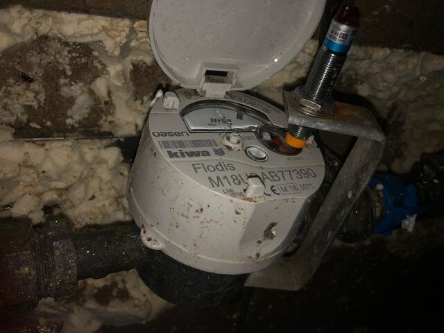
The sensor should be placed on the side of the rotator, not in the middle.
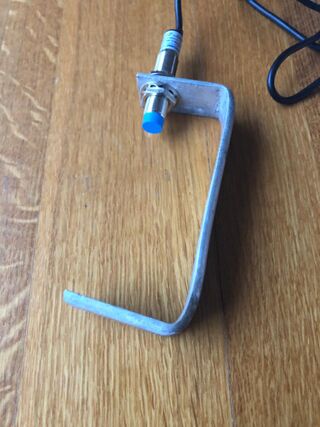
With a piece of aluminium it's easy to mount on the meter:
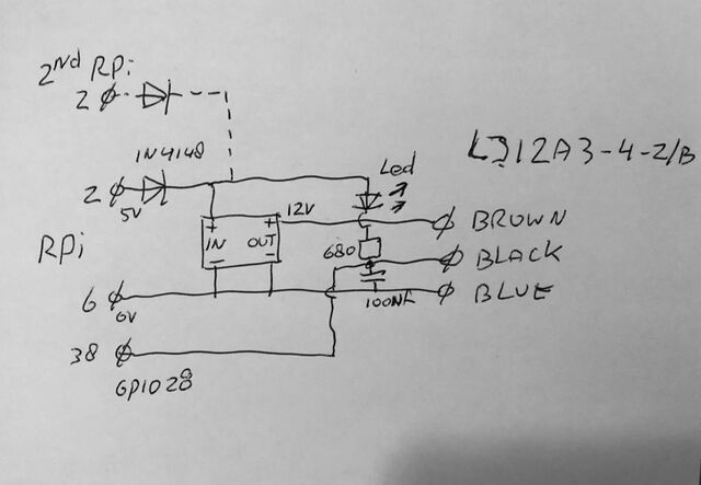
Shematics:
The sensor needs 9-36 Volt, a Raspberry Pi only can deliver 5 and 3.3 Volt.
You can use an extra 12 Volt adapter, but I don't like that......
I use an adjustable chopper board (also from China), adjusted as 12 Volt.
If you want the same Board it's called:
"MT3608 DC-DC Adjustable Boost Module Feed Converter Voltage Regulator Module 2A Max 2 V-24 V to 5 V-28 V"
Update: There are also sensors working at 5 Volt, this is a lot easier. In the time I build this, I didn't find them.
The output is connected to one of the GPIO's of the Pi, which first should configured as input, in my case I use GPIO28 (pin38/BCM20).
The led will show if it works, for every pulse 1 liter water is detected.
The diode is not needed if you use 1 Pi.
I use a Raspberry Pi Cluster, so I can do a failover.
The board is connected on 1 Pi, the other Pi is connected to the same pins: 6 and 38.
For the Power (pin 2) a diode is needed, 1 for each Pi, while it's a bad idea to connect the power to multiple Pi's.
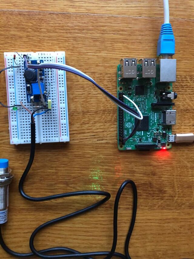
First tested it with an experiment board:
To test it on a pi you need the gpio command:
if not installed:
sudo apt-get update
sudo apt-get install wiringpi
change GPIO 28 (BCM=20 and pin=38) as input:
sudo /usr/local/bin/gpio export 20 in
Put this line somewhere in a startup file, so it will stay that way, after reboot,
best below in /etc/rc.local (without sudo)
to show the states:
sudo gpio readall
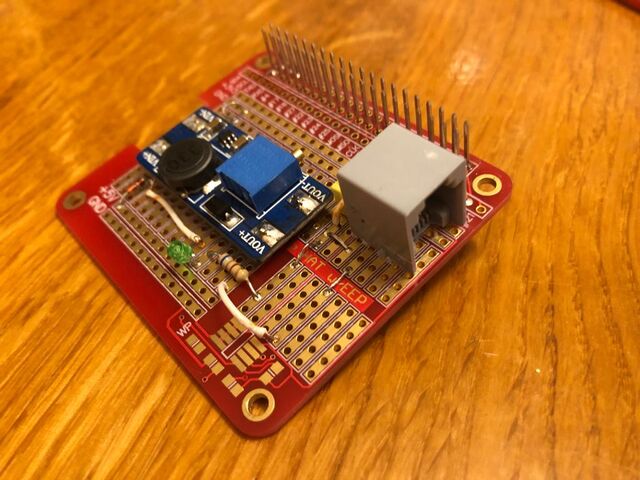
This is the result:
All welded on an experiment board, for the Rpi, with a long pin connector, so you can stack other boards.
I use a RJ11 connector to connect the sensor.
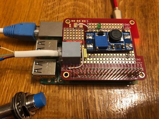
Complete mounted on the Pi:
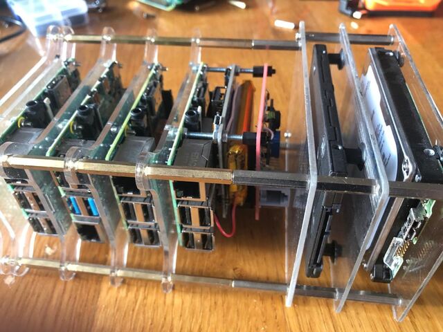
Mounted in my Pi-Cluster, above the UPS-board:
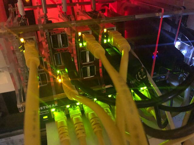
Yust like a Christmas-Tree:
To get is working in Domotics:
Add "Generic sysfs GPIO" at Hardware.
The GPIO device will be added automatically after 1 pulse, I named it "WaterMeterPulse"
Add a virtual Sensor type "RFXMeter counter", I Called it "WaterMeter"
To get it working, add a lua script:
   -- sript_WaterMeter.lua
   -- 2018-09-04 v1.00 Roland Breedveld
   commandArray = {}
       if (devicechanged['WaterMeterPulse'] == 'Open') then
           water=otherdevices['WaterMeter']
           print("water impulse received: current liter: " .. water)
           water = water + 1
           --change 372 tot the ID of your WaterMeter device.
           commandArray['UpdateDevice']='372|0|'..water
       end
   return commandArray
Update: Arnold Kamminga wrote a plugin for domoticz, much easier to use:
https://github.com/akamming/domoticz-watermeter
Partlist:
Total Costs: about 10 Euro
I ordered most parts at the well known Chinese site.
- LJ12A3-4-Z/B magnetic sensor
- aluminium strip 20x2.5cm, bended:4.5-11-4.5cm, with a ca 12mm hole
- MT3608 DC-DC Adjustable Boost Module Feed Converter Voltage Regulator (or external 12 Volt power supply)
- Led 2mm, green or red.
- resistor 680 Ohm
- capacitor ca. 100 nF
- RPi experiment board, I used: "DIY Proto HAT Shield Extension Board for Raspberry Pi GPIO Board"
- Connector, with long pins: "20 Pins Female Pin Header 2.54m Pitch Extra Tall Female Dual Row Short Pin Headers PCB Connector"
- optional: diode 1N4148 or something like that (1 for each RPi)
- RJ11 connector, but every other connector will be fine.
